- This topic is empty.
-
AuthorPosts
-
26/10/2026 at 17:18 #82613
Selecting the right U-tube heat exchanger is an important step in designing an efficient and reliable thermal management system. Whether the equipment is used in industrial processing, HVAC systems, cooling applications, or heat recovery, the heat exchanger must meet specific operating requirements to deliver consistent performance. An unsuitable design can lead to insufficient heat transfer, excessive pressure drop, higher energy consumption, maintenance difficulties, and unnecessary operating costs.
A U-tube heat exchanger is commonly associated with shell-and-tube equipment that uses U-bent tubes to transfer heat between two fluids. Its design allows thermal expansion within the tube bundle and can simplify certain maintenance procedures. However, the most appropriate configuration depends on the operating temperature, pressure, fluid properties, required heat duty, installation space, and maintenance expectations.
It is also important to distinguish a conventional U-tube heat exchanger from a U-shaped heat pipe. Although the terms sound similar, they describe different heat transfer technologies. A conventional U-tube heat exchanger transfers heat between fluids flowing through separate passages, while a heat pipe uses a sealed working fluid and phase-change process to transport thermal energy. Understanding this distinction is particularly important when selecting equipment for HVAC air treatment and industrial dehumidification.
This guide explains the key factors to consider when choosing a U-tube heat exchanger, helping engineers, equipment manufacturers, and purchasing teams make informed decisions based on actual application requirements.
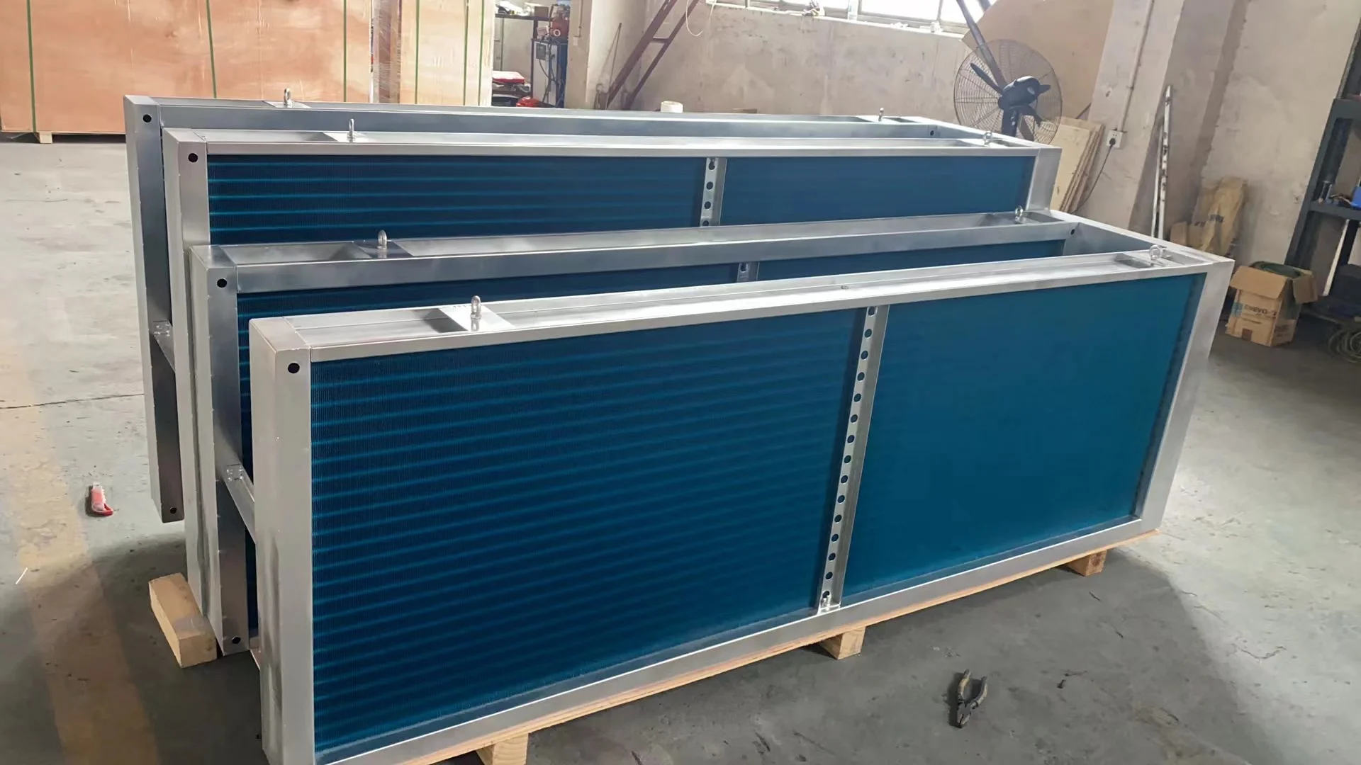
1. Understand the Application and Heat Transfer Requirements
The first step in selecting a suitable U-tube heat exchanger is to define what the equipment needs to accomplish. Different applications require different levels of heat transfer, temperature control, and operational flexibility.
For example, an industrial process may require a hot fluid to be cooled to a specific outlet temperature. A heating application may need to transfer energy from steam or hot water to another fluid. In an HVAC system, a heat exchanger may be used to recover energy and improve the overall efficiency of air conditioning equipment.
Before comparing products, identify the primary objective of the heat exchanger.
Determine the Required Heat Duty
Heat duty refers to the amount of thermal energy that must be transferred per unit of time. It is one of the most important parameters when sizing a U-tube heat exchanger.
For a fluid experiencing a temperature change, the heat duty can often be estimated using the following relationship:
\[
Q=\dot{m}c_p(T_{\mathrm{in}}-T_{\mathrm{out}})
\]Where:
-
\(Q\) is the heat transfer rate.
-
\(\dot{m}\) is the fluid mass flow rate.
-
\(c_p\) is the specific heat capacity.
-
\(T_{\mathrm{in}}\) is the inlet temperature.
-
\(T_{\mathrm{out}}\) is the outlet temperature.
For a cooling process, the temperature difference represents the reduction in fluid temperature. For a heating process, the corresponding temperature rise is used.
In systems involving two fluids, the heat lost by the hot stream should approximately equal the heat gained by the cold stream, after accounting for heat losses to the surroundings.
Providing the manufacturer with the required heat duty and operating conditions helps prevent undersizing or unnecessary oversizing.
Identify the Required Outlet Temperature
The desired outlet temperature determines how much heat must be transferred and influences the exchanger's required surface area.
If the outlet temperature requirement is particularly demanding, the design may need a larger heat transfer surface, a different tube arrangement, or a more suitable flow configuration.
Engineers should also consider how much the inlet conditions vary during normal operation. A heat exchanger designed only for one ideal operating point may not deliver the same performance when flow rates or inlet temperatures change.
2. Evaluate Operating Temperature and Pressure
Temperature and pressure affect the selection of tube materials, shell construction, tube wall thickness, joints, and overall mechanical design.
A U-tube heat exchanger intended for moderate-temperature water service may have different construction requirements from one designed for high-temperature oil, steam, or an industrial process involving elevated pressure.
Operating Temperature Range
Determine the minimum, normal, and maximum operating temperatures for both fluid streams.
Temperature differences between the tubes and shell can cause thermal expansion. One advantage of a U-tube heat exchanger is that the curved tube section can accommodate differential expansion more readily than some rigid tube-bundle arrangements.
This feature can make U-tube designs attractive for applications involving significant temperature differences between the shell and tube sides.
However, the U-shaped section must still be designed appropriately. Tube bending, wall thickness, material properties, and the minimum bend radius all influence structural reliability.
Design Pressure
The design pressure should account for the maximum pressure expected under the specified operating and abnormal conditions, as required by the applicable design code.
The tube side and shell side may operate at different pressures, so each side must be evaluated separately.
When selecting a U-tube heat exchanger manufacturer, confirm that the proposed equipment can meet the required pressure and temperature ratings. For regulated industrial applications, verify the applicable pressure vessel codes, inspection requirements, and documentation before ordering.
3. Choose Suitable Tube and Shell Materials
Material selection affects heat transfer performance, corrosion resistance, mechanical strength, durability, and total ownership cost.
The right material depends primarily on the fluids being handled and the conditions under which the heat exchanger operates.
Thermal Conductivity
Tube materials influence how readily heat passes through the tube wall. Copper and aluminum offer relatively high thermal conductivity and are common in many heat transfer applications, particularly HVAC coils and air-side heat exchangers.
Stainless steel and other engineering alloys may be preferred where strength, temperature resistance, corrosion resistance, or process compatibility is more important than maximizing conductivity alone.
For conventional industrial U-tube heat exchangers, materials such as carbon steel, stainless steel, copper alloys, and specialized alloys may be considered depending on the service conditions.
The material should be selected as part of the complete thermal and mechanical design rather than according to conductivity alone.
Corrosion Resistance
Corrosion can reduce tube wall thickness, weaken connections, contaminate the process fluid, and eventually cause leakage.
Before selecting a material, evaluate the chemical composition of both fluids, operating temperatures, pressure, pH where relevant, and the presence of chlorides or other corrosive substances.
For example, a material that performs well with clean water may not be suitable for a process fluid containing aggressive chemicals.
Ask the manufacturer to explain the material options available for your application and identify any limitations that could affect the expected service life.
Fouling and Cleaning Requirements
Some fluids contain suspended solids, dissolved minerals, oils, or other substances that accumulate on heat transfer surfaces.
This buildup, known as fouling, can reduce heat transfer efficiency and increase pressure drop.
When selecting a U-tube heat exchanger for industrial applications, consider the fluid's tendency to form deposits and the cleaning methods available. Tube diameter, fluid velocity, material selection, and maintenance access can all influence long-term performance.
The U-shaped tube bundle may make mechanical cleaning of the curved sections more difficult in some configurations. If mechanical tube cleaning is essential, confirm that the proposed design supports the intended cleaning procedure.
4. Consider Flow Rate and Fluid Properties
The flow rates and physical properties of both fluids have a major influence on heat transfer performance.
A heat exchanger that performs well at one flow rate may be less effective when the flow changes significantly.
Fluid Flow Rate
The mass or volumetric flow rate determines how much fluid passes through the equipment during a given period.
Higher flow rates can increase the heat transfer coefficient by improving turbulence, but they may also increase pressure drop and pumping power requirements.
Lower flow rates can reduce pressure drop, yet may produce insufficient heat transfer or encourage fouling in certain applications.
Therefore, the goal is not simply to maximize flow velocity. The flow conditions should balance thermal performance, hydraulic resistance, energy consumption, and equipment limitations.
Viscosity and Specific Heat
Fluid viscosity affects how easily the fluid flows through the tubes and shell. Highly viscous fluids may produce higher pressure losses and lower heat transfer coefficients under certain conditions.
Specific heat capacity determines how much energy a fluid absorbs or releases as its temperature changes.
Density, thermal conductivity, and phase behavior should also be considered. These properties affect both the heat duty calculation and the hydraulic design.
Providing accurate fluid property data helps the manufacturer select appropriate tube dimensions, pass arrangements, and shell-side configurations.
5. Assess Heat Transfer Area and Tube Configuration
The heat transfer area is a major factor in determining the size and performance of a U-tube heat exchanger.
In general, the required heat transfer area depends on the heat duty, overall heat transfer coefficient, and effective temperature difference between the two fluid streams.
A commonly used relationship is:
\[
Q=UA\Delta T_{\mathrm{lm}}
\]Where:
-
\(Q\) is the heat transfer rate.
-
\(U\) is the overall heat transfer coefficient.
-
\(A\) is the effective heat transfer area.
-
\(\Delta T_{\mathrm{lm}}\) is the log mean temperature difference.
The appropriate correction factors and calculation method depend on the heat exchanger configuration and flow arrangement.
Tube Length and Diameter
Longer tubes can provide more heat transfer area within a given bundle arrangement, but they may also increase pressure drop and affect maintenance requirements.
Tube diameter influences flow velocity, heat transfer, pressure loss, and the number of tubes that can fit within the available shell dimensions.
The best combination depends on the heat duty and fluid characteristics.
Number of Tube Passes
The number of tube passes affects the fluid velocity and temperature distribution inside the heat exchanger.
Increasing the number of passes can raise tube-side velocity for a given flow rate, potentially improving heat transfer. However, it may also increase pressure drop.
The manufacturer should evaluate tube-pass arrangements together with the required thermal performance and pumping limitations.
U-Bend Geometry
The U-shaped section allows tubes to return through the bundle without requiring a separate return connection for each tube.
However, the bend geometry must be designed to avoid excessive tube thinning, deformation, or mechanical stress during manufacturing.
When comparing U-tube heat exchanger designs, ask how tube bending quality and dimensional consistency are controlled.
6. Balance Heat Transfer Efficiency and Pressure Drop
A high heat transfer rate is not the only measure of a good heat exchanger. The energy needed to circulate the fluids must also be considered.
Pressure drop is the reduction in fluid pressure as it moves through the tubes, shell, and other internal passages.
If the pressure drop is excessive, pumps or fans may need to consume more energy to maintain the required flow rate.
Evaluate Tube-Side Pressure Drop
Tube-side pressure drop depends on tube length, diameter, roughness, fluid viscosity, flow velocity, and the number of passes.
For liquids, the pump must provide sufficient pressure to overcome this resistance as well as the rest of the system's hydraulic losses.
The allowable pressure drop should therefore be defined before finalizing the design.
Evaluate Shell-Side Pressure Drop
Shell-side flow is affected by the shell diameter, baffle arrangement, tube layout, and fluid properties.
Baffles can improve heat transfer by directing fluid across the tube bundle, but they can also increase pressure loss.
The appropriate configuration depends on the relative importance of thermal performance, pumping energy, vibration risk, and fouling behavior.
A well-designed U-tube heat exchanger should provide the required heat duty without creating unnecessary hydraulic resistance.
7. Check the Suitability of the Heat Exchanger for HVAC and Dehumidification
Although conventional U-tube heat exchangers are widely used for liquid-to-liquid and other industrial heat transfer duties, some HVAC applications require a different type of heat recovery equipment.
This distinction is important when the goal is to recover energy during air dehumidification.
Conventional U-Tube Heat Exchangers
A conventional U-tube heat exchanger typically transfers heat between two fluid streams. One fluid flows through the tubes, while the other flows around the tube bundle within the shell.
These systems are suitable for many industrial heating and cooling duties, including applications where thermal expansion accommodation is important.
U-Shaped Heat Pipes for Air Dehumidification
A U-shaped heat pipe used in air handling operates differently. It transfers thermal energy through a sealed working fluid that evaporates in the warmer section and condenses in the cooler section.
In a typical dehumidification configuration, one section pre-cools incoming air before it reaches the cooling coil. After moisture removal, the other section reheats the treated air.
This arrangement can reduce the external energy required for reheating, depending on the temperature difference and operating conditions.
When selecting equipment for HVAC heat recovery, clarify whether your application requires a conventional U-tube heat exchanger or a U-shaped heat pipe heat exchanger. Selecting the correct technology is more important than matching a product name alone.
8. Consider Installation Space and System Integration
The available installation space can significantly influence heat exchanger selection.
For replacement projects, the equipment may need to fit within an existing shell, skid, air handling unit, or process line. For new installations, the heat exchanger dimensions should be coordinated with the overall system layout.
Consider the following factors:
-
Overall equipment dimensions
-
Tube bundle removal or maintenance clearance
-
Fluid inlet and outlet locations
-
Pipework routing
-
Support and mounting requirements
-
Drainage and venting arrangements where applicable
-
Access for inspection and cleaning
For HVAC applications, also consider airflow direction, casing dimensions, cooling coil position, and access to condensate drainage.
A manufacturer that reviews the complete installation arrangement can help identify dimensional conflicts before production begins.
Conclusion
Selecting the right U-tube heat exchanger requires a comprehensive assessment of thermal performance, operating pressure and temperature, fluid properties, materials, flow conditions, pressure drop, installation constraints, and maintenance requirements. Rather than choosing equipment based on size or initial price alone, buyers should evaluate how well the design meets the application's actual operating conditions.
For industrial heat transfer duties, a properly selected U-tube heat exchanger can provide reliable performance while accommodating thermal expansion and supporting practical maintenance. For HVAC applications involving air dehumidification and heat recovery, it is equally important to distinguish conventional U-tube equipment from U-shaped heat pipe systems, since their working principles and installation requirements differ.
By preparing accurate specifications and working with a manufacturer that understands the relevant heat transfer technology, businesses can make more informed equipment decisions. Novel provides heat pipe and air handling solutions for different HVAC and dehumidification requirements, helping customers evaluate suitable configurations for efficient heat recovery and reliable air treatment.
http://www.nowvleco.com
nowvleco -
-
AuthorPosts

- You must be logged in to reply to this topic.